AI Image Created By Flux AI Image Generator
Prompt
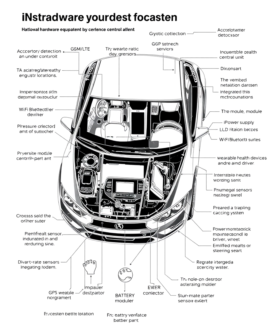
Create a detailed hardware name black and white sketch of a car equipped with an advanced accidental alert system, focusing on the hardware components and their specific installation locations. The microcontroller/processor should be shown mounted under the dashboard or in a central control unit. Illustrate the accident detection sensors, with the accelerometer and gyroscope integrated into the vehicle’s central control unit or under the dashboard, and impact sensors placed at strategic points around the vehicle (front, rear, and sides). Depict the communication modules, including the GSM/LTE module under the dashboard or in the central control unit, and the Wi-Fi/Bluetooth module integrated with the microcontroller. Show the GPS module mounted on the dashboard or integrated into the vehicle’s navigation system. Include the health monitoring devices such as wearable health devices worn by the driver on their wrist, an infrared camera mounted on the dashboard facing the driver, pressure sensors integrated into the steering wheel, and a heart rate monitor embedded in the driver’s seat or steering wheel. Display the power supply with the battery pack mounted in the trunk or under the rear seat. Illustrate the user interface components, including the LCD/TFT display mounted on the dashboard within the driver’s line of sight, a buzzer/alarm integrated into the dashboard, and LED indicators positioned on the dashboard. Show the data storage with the SD card module integrated with the microcontroller/processor. Additionally, depict the necessary wiring connecting all components, running neatly through the vehicle. The sketch should clearly depict the placement of each hardware component within the car, providing a comprehensive visual representation of their integration in the accidental alert system.
Image Analysis
Emotional Analysis
Application Scenarios
Car Accident Detection
Description: Example Scenario for advanced vehicle safety.
Potential Use: The system can automatically alert emergency services in the event of an accident.
Health Monitoring
Description: Real-time health monitoring during drives.
Potential Use: Checks driver's health metrics and alerts if anomalies are detected.
Usage Data Analytics
Description: Data analysis for improving vehicle safety features.
Potential Use: Collects and analyzes driving data to enhance future safety protocols.
Emergency Response
Description: Driver assistance in emergencies.
Potential Use: Provides immediate step-by-step guidance to the driver post-accident.
Smart Vehicle Interaction
Description: Integration with smart city infrastructure.
Potential Use: Communicates with traffic management systems for improved navigation and safety across the city.
Technical Analysis
Quality Assessment: High-quality generation with clear component placement.
- Comprehensive system integration shown clearly
- Variety of health monitoring features included
- Incorporation of communication modules for connectivity
- Detail-oriented sketch representation promotes understanding
- Optimize module integration for space efficiency
- Enhance sensor accuracy for real-time data reading
- Improve communication latency between components
- Simplify wiring setup for easier troubleshooting